
EMS vs BMS vs SCADA vs PPC
EMS vs BMS vs SCADA vs PPC: clear definitions, authority boundaries, protocols, and a comparison table for BESS project developers and energy executives.
When a utility-scale BESS project fails its FCR prequalification test, the post-mortem rarely identifies a cell fault or a hardware failure at the root cause. More often, the diagnosis comes back to a system boundary that nobody defined precisely enough during engineering. EMS was waiting for a setpoint, the PPC was issuing one, the SCADA was logging the confusion, and the BMS was doing exactly what it was designed to do: protect the cells, regardless of what anyone else in the stack intended. That kind of operational failure is surprisingly common, and it begins as a misunderstanding in the procurement phase.
Four control systems sit inside every serious BESS deployment — the Energy Management System (EMS), the Battery Management System (BMS), the Supervisory Control and Data Acquisition system (SCADA), and the Power Plant Controller (PPC). Each one carries a distinct function, operates at a different layer of the control hierarchy, and speaks to the rest of the plant through different protocols at different response speeds. Conflating them — or assigning responsibilities to the wrong layer during design — produces projects that either underperform commercially or fail grid compliance altogether.
This article defines each system with precision, maps the boundaries between them, and addresses the misconceptions that routinely surface in project development, procurement, and commissioning.
Four Systems, One Stack: Why the Confusion Exists
The terms EMS, BMS, SCADA, and PPC each appear in energy storage project documentation — often in proximity, occasionally as synonyms, and sometimes in direct contradiction. A developer's RFP might describe an "EMS" that includes SCADA functionality. A hardware vendor's datasheet might fold BMS data directly into what they label an "energy management platform." A grid operator's grid code requirement document will reference a PPC without distinguishing its role from the plant-level EMS above it.
Part of the confusion is historical. Many of these systems evolved independently, from different engineering disciplines, before large-scale battery storage created the need for a tightly integrated control stack. SCADA has its roots in industrial process automation. BMS technology emerged from electric vehicle and consumer electronics battery design. PPC is a concept borrowed from conventional generation, where a single controller manages a turbine's output relative to grid signals. EMS, as applied to BESS, is arguably the newest and most conceptually broad category.
The other source of confusion is commercial. Many vendors offer systems that combine two or more of these functions under a single product label, making it harder to identify where one system ends and the next begins. The practical question for any energy project developer, plant operator, or C&I energy manager is not which vendor's label to trust — it is what functional capabilities each layer must deliver, and whether those capabilities are actually present in the systems being procured.
What an Energy Management System (EMS) Actually Does
The EMS as the Decision Layer
The Energy Management System is the intelligence layer of a BESS deployment. Its job is not simply to pass commands down to hardware — it is to decide what those commands should be, at every moment, based on a simultaneous reading of energy prices, grid conditions, load demand, battery state, and contracted obligations. The EMS translates commercial intent into operational reality.
In a utility-scale project, that means the EMS holds the dispatch logic for FCR (Frequency Containment Reserve), aFRR (automatic Frequency Restoration Reserve), day-ahead energy arbitrage, and intraday trading — all simultaneously, with the system cycling between these revenue streams based on real-time market conditions and prequalification windows. In a C&I deployment, the EMS monitors incoming demand curves, predicts peak periods using load-following algorithms, and decides when to charge from the grid or discharge to the facility to minimise peak demand charges and maximise self-consumption from on-site PV.
This is operationally complex. A well-configured EMS must hold multiple control objectives in tension: protecting battery longevity while maximising revenue, respecting grid code limits while responding to intraday price signals, managing EV charging demand while maintaining facility backup capacity. All of these decisions happen in a control loop measured in milliseconds, not minutes.
Critically, the EMS must be vendor-neutral. In a real-world BESS fleet, the battery modules might come from one manufacturer, the power conversion system from another, and the site's legacy plant systems may include multiple SCADA data sources and third-party monitoring tools. An EMS that cannot communicate across this heterogeneous hardware environment through standard protocols — Modbus TCP, IEC 61850, IEC 104, REST API — will create integration bottlenecks that erode project value from day one.
Operators managing utility-scale EMS deployments require a system that can hold prequalification status for multiple ancillary services simultaneously while executing automated market bids without human intervention between dispatch events. That requires a control architecture fundamentally different from legacy SCADA-with-setpoints approaches.
Battery Management System (BMS): The Cell-Level Guardian
The Battery Management System exists for one purpose: to keep the battery cells alive and safe. It measures cell voltage, temperature, and current at the hardware level, executes cell balancing to distribute charge evenly across the pack, and enforces hard limits on charge and discharge rates based on electrochemical constraints. When a cell temperature threshold is breached or a voltage excursion occurs, the BMS acts — immediately, without waiting for instructions from the EMS or any other system.
This is a critical design principle. The BMS does not operate on a schedule. It does not interpret market signals. It does not know whether the project is contracted for FCR or running an energy arbitrage strategy. The BMS knows only cell-level physics, and it responds to deviations from safe operating parameters with override authority that supersedes everything above it in the control stack.
What BMS Cannot Do Alone
A BMS cannot manage energy dispatch, integrate with trading platforms, execute peak shaving logic, or communicate with the grid in any commercially meaningful way. It has no awareness of demand charges, balancing market windows, or contracted ancillary service obligations. Its communication protocols — typically CAN Bus, RS485, or proprietary serial interfaces — are designed for low-latency hardware communication, not for the data exchange requirements of plant-level or market-level operations.
This means the BMS and the EMS must coexist with clearly defined authority boundaries. The EMS sets operational setpoints within a safe envelope. The BMS can override those setpoints if cell conditions require it. The failure mode of unclear authority — an EMS that does not receive real-time BMS data, or a system integration that allows EMS commands to bypass BMS limits — is one of the more dangerous configurations in a BESS deployment.
It is also worth noting that BMS firmware is typically proprietary to the battery manufacturer, which makes vendor-neutral EMS architecture even more important. The EMS must be capable of ingesting data from different BMS implementations and translating their state information into a unified operational picture.
⚙ TECHNICAL NOTE — BMS OVERRIDE BEHAVIOUR
In a correctly integrated BESS stack, the BMS holds unconditional override authority over charge/discharge commands. When a BMS trips — due to a cell over-temperature event or voltage excursion, for example — the EMS will lose setpoint acknowledgement from the PCS. A well-designed EMS should detect this loss of response within its control loop and flag the event immediately through the alarm management system, without re-issuing the command. Systems that re-attempt setpoints after BMS-level trips without confirming the override cause are a known commissioning risk, particularly in high-C-rate fast frequency response applications where the EMS is sending commands at sub-second intervals.
SCADA in Energy Storage: Visibility Without Control Authority
Supervisory Control and Data Acquisition systems were designed to give operators a window into large, geographically distributed industrial processes. In energy storage, SCADA serves that same function: it aggregates data from the plant — including readings from the EMS, BMS, PCS, energy analysers, and environmental sensors — presents it in a human-readable format, logs historical data to a historian, and raises alarms when defined thresholds are breached.
In most well-designed BESS deployments, SCADA is a read layer, not a control layer. Operators can see what is happening in real time across the entire plant, access historical trends, acknowledge alarms, and in some configurations issue manual overrides during maintenance windows. But the continuous, automated control of energy flows — dispatch decisions, market participation, charge/discharge sequencing — is not SCADA's domain. Pushing those functions into a SCADA system is a legacy approach that limits the responsiveness and commercial performance of a modern BESS project.
Where SCADA Fits in a Modern BESS Project
SCADA's genuine value in a BESS context is in the operations and maintenance workflow. A well-integrated SCADA layer enables maintenance engineers to diagnose anomalies without physical site access, cross-reference alarm histories against energy production logs, and identify patterns — a recurring BMS cell imbalance, a PCS current spike at specific load conditions — that would be invisible to an EMS focused solely on dispatch logic.
For multi-site fleet operators, SCADA also provides the unified visibility layer that allows a central operations team to monitor many projects simultaneously. The EMS at each site handles automated dispatch; the SCADA layer rolls up status across the portfolio.
In projects where a legacy SCADA system is already in place — a common scenario in brownfield industrial deployments — the EMS must be capable of integrating with that existing infrastructure through open protocols. A third-party SCADA system that communicates via OPC-UA or Modbus TCP should present no barrier to a well-architected EMS.
Power Plant Controller (PPC): The Grid Interface Layer
The Power Plant Controller handles the interface between the energy storage plant and the transmission or distribution grid. Its primary functions are reactive power control, voltage regulation, power factor correction, and frequency response — the set of obligations that a grid operator imposes on a connected generator or storage asset as a condition of grid access.
Where the EMS manages the economics and operational strategy of a BESS, the PPC manages grid compliance. In practice, this means the PPC holds the logic for P-f droop control — the automatic adjustment of active power output in response to grid frequency deviations — and for reactive power dispatch in response to voltage signals at the point of common coupling. These are fast responses: grid frequency deviations trigger PPC action in the 100-millisecond range, and in some grid codes the full droop response must be delivered within a few hundred milliseconds of the triggering event.
PPC vs EMS: Where One Ends and the Other Begins
The boundary between PPC and EMS is one of the most commonly misunderstood in BESS project design. A useful way to frame it: the PPC responds to the grid; the EMS decides how to position the asset relative to the market. The PPC might reduce active power output because a voltage excursion requires reactive power injection. The EMS, receiving that constraint, adjusts its dispatch strategy accordingly — pulling back on an aFRR bid or delaying a scheduled discharge. The two systems must communicate, but they are not interchangeable.
In utility-scale renewable-plus-storage projects, the PPC is typically a dedicated hardware controller at the substation level, prequalified with the TSO for specific grid services. The EMS sits above it, issuing setpoint updates within the PPC's operating envelope. In some configurations — particularly where the EMS architecture includes a dedicated field controller — the PPC and EMS functions can be integrated into a single physical platform, but the functional separation of grid compliance from energy optimisation should always be preserved in the software architecture.
For C&I deployments where peak shaving and load management are the primary objectives, a dedicated PPC may not be required. The Commercial & Industrial EMS solutions needed in those environments focus on demand response, load following, and EV charge management rather than transmission-level grid compliance.
⚙ TECHNICAL NOTE — PPC PREQUALIFICATION AND EMS SETPOINT LATENCY
FCR and aFRR prequalification tests require that a BESS plant demonstrate defined power response curves within strict time tolerances — typically 30 seconds to full activation for aFRR, and a continuous droop response for FCR. If the EMS is imposing scheduling decisions that conflict with the PPC's required response envelope during a prequalification test, the asset will fail. The safest architecture separates PPC droop response as a hardware-level function that the EMS cannot override during an active frequency event, with the EMS only modifying state-of-charge targets and scheduling windows outside active response windows.
How the Four Layers Work Together
The most accurate mental model for these four systems is a vertical hierarchy of authority and speed. At the bottom, the BMS operates at the hardware level — microsecond responses to cell conditions, with override authority over everything above it. Above that, the PPC handles grid-side compliance at sub-second to second timescales. The EMS sits above both, setting the strategic operating position of the asset across minutes, hours, and trading windows. SCADA spans the full stack horizontally, providing visibility into all layers without primary control authority over any of them.
In a well-integrated deployment, command flow works top-down for scheduling and strategy, and bottom-up for safety constraints and overrides. The EMS issues a dispatch setpoint to the PCS. The BMS validates that the command is within the safe operating envelope and executes. The PPC monitors the resulting active power output and adjusts reactive power to maintain grid compliance. SCADA logs the entire sequence and raises an alarm if any layer fails to respond within expected parameters.
Protocol compatibility is where theory meets engineering reality. The EMS must maintain live communication with the BMS data (read-only, for SOC/SOH state awareness), with the PCS (read-write, for active power setpoints), with the PPC (bidirectional, for constraint coordination), and with external market platforms (for trading and ancillary service bidding). Each of these interfaces operates on different protocols, at different polling rates, with different data structures. The EMS's ability to manage this protocol complexity without latency accumulation is what determines real-world system performance.
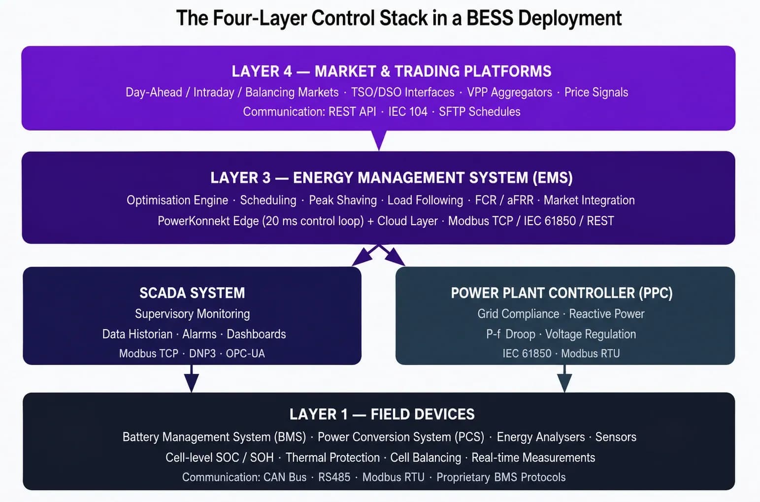
Figure 1: The four-layer control stack in a grid-scale BESS deployment. Commands flow top-down; safety overrides flow bottom-up.
System Comparison at a Glance
The table below summarizes the functional boundaries, authority model, and key characteristics of each system. These distinctions should drive the requirements definition phase of any BESS project — and they are the questions that a rigorous technical procurement process will test.
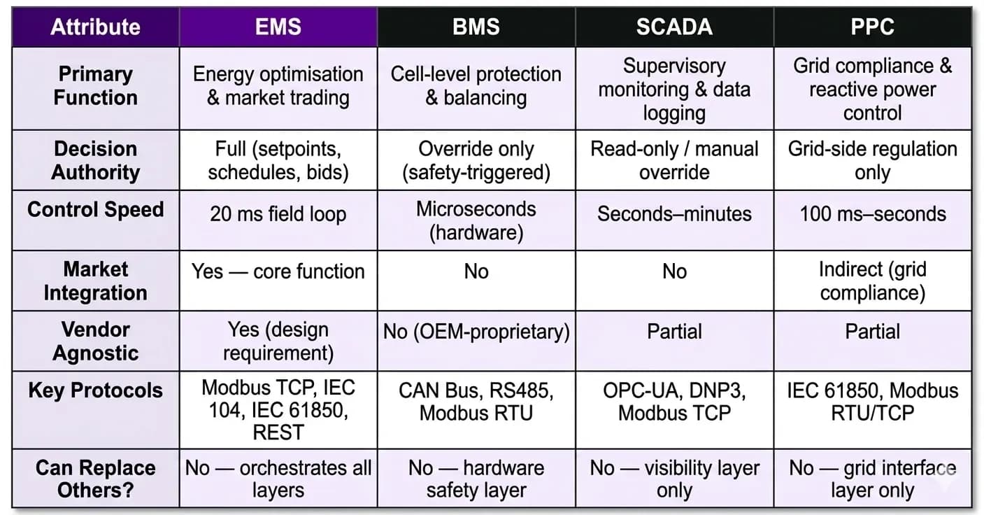
Table 1: EMS vs BMS vs SCADA vs PPC — functional boundaries and key attributes.
Side-by-Side System Profiles
The comparison is reinforced visually below. Note particularly the columns for decision authority and market integration — these are the attributes that most commonly drive value in utility-scale and C&I commercial deployments, and they are functions that only the EMS is designed to deliver.
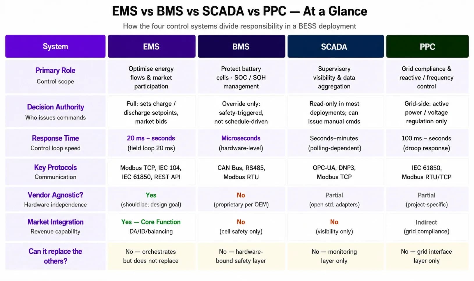
Figure 2: At-a-glance comparison of the four BESS control systems across seven key attributes.
Common Misconceptions in Procurement and Project Design
Several specific misconceptions recur across project development processes and RFP documentation in this industry.
The first is the idea that a SCADA system can replace an EMS. It cannot. SCADA provides visibility; it does not hold optimisation logic, market connectivity, or automated dispatch capability. Facilities that configure a SCADA system as their primary control interface are dependent on human operators to issue every meaningful operational command — a model that is incompatible with frequency response services, intraday trading, or any revenue stream that requires sub-minute automated action.
The second misconception is that a sophisticated BMS removes the need for an EMS. The BMS operates within the electrochemical constraints of the battery. It has no commercial awareness, no market integration, and no load-following capability. State-of-charge management by the BMS alone — charging when the grid is available, discharging when commanded — is operationally inefficient and commercially inert.
The third is treating the PPC as an EMS. A PPC is a compliance tool, not a commercial optimisation engine. It ensures the asset meets the grid operator's technical requirements. Revenue is not its objective, and it lacks the forecasting, scheduling, and market connectivity needed to generate it.
Finally, the most damaging misconception in multi-vendor project teams is the assumption that system integration between these four layers is a commissioning task rather than a design task. Protocol compatibility, data mapping, alarm hierarchies, and authority boundary definitions must be specified during engineering — not discovered during site commissioning under time pressure. Projects that leave integration to the installation phase routinely overrun commissioning schedules, and some never achieve the operational performance their financial models assumed.
Assessing your BESS control architecture? PowerKonnekt EMS integrates EMS, market connectivity, and third-party SCADA interfaces in a single vendor-neutral platform.
Request a free two-week demo at powerkonnekt.com
The Integration Question: Who Sends Commands to Whom
A structured view of command authority across the four layers resolves most integration conflicts before they occur. The correct hierarchy, in a utility-scale configuration, is:
- Market and trading platforms issue schedules and bid confirmations to the EMS via REST API, SFTP, or IEC 104.
- The EMS translates these market instructions into operational setpoints — active power targets, SOC limits, frequency response activation windows — and issues them to the PCS and PPC via Modbus TCP or IEC 61850.
- The PPC applies grid compliance constraints (reactive power, voltage regulation) to the active power output without modifying the EMS's charge/discharge strategy unless a grid fault condition requires it.
- The BMS monitors cell-level conditions continuously and enforces safety overrides that take precedence over all setpoints issued by systems above it.
- SCADA receives data from all layers, logs it, presents it to operators, and raises alarms — without issuing commands in normal operations.
Deviations from this hierarchy — an EMS that cannot receive BMS state data in real time, a PPC whose constraints are not visible to the EMS scheduling logic, or a SCADA layer that bypasses the EMS to issue direct PCS commands — are design flaws with measurable commercial consequences.
The full range of integration capabilities available in a purpose-built EMS — including third-party SCADA connectivity, protocol bridge functions, and VPP aggregation — is described on the PowerKonnekt solutions page.
Frequently Asked Questions
What is the difference between an EMS and a BMS in a battery storage system?
An EMS (Energy Management System) manages the operational strategy of the entire BESS — including dispatch, market trading, peak shaving, and load optimisation — at the plant level. A BMS (Battery Management System) manages the electrochemical safety of the battery cells themselves, enforcing voltage, current, and temperature limits. The two systems operate at different layers: the EMS directs commercial behaviour; the BMS enforces hardware safety and holds override authority if cell conditions are breached.
Can SCADA replace an EMS in a commercial BESS project?
No. SCADA systems are designed for supervisory monitoring and data aggregation — they provide visibility into plant operations but do not hold the optimisation logic, market integration, or automated dispatch capability that an EMS delivers. Using a SCADA system as the primary control interface in a project contracted for ancillary services or energy arbitrage means relying on human operators for every commercial decision, which is incompatible with the response times and automation requirements those revenue streams demand.
What does a Power Plant Controller (PPC) do in a BESS project?
A PPC manages the compliance interface between the BESS and the transmission or distribution grid. It handles reactive power control, power factor correction, voltage regulation, and P-f droop response — the obligations that grid operators impose on connected storage assets. The PPC ensures the asset meets grid code technical requirements. It is not an optimisation tool; revenue generation and market integration are the EMS's domain, not the PPC's.
Does every BESS deployment need all four systems?
Not necessarily at the same scale. A C&I behind-the-meter installation focused on peak shaving and self-consumption may not require a standalone PPC; those functions may be embedded within the EMS field controller. A utility-scale plant contracted for FCR or aFRR will require a dedicated PPC prequalified with the TSO. SCADA may be a separate platform or integrated into the EMS cloud layer. The architecture depends on grid connection requirements, the services contracted, and the facility's operational scale.
What protocols connect an EMS to the BMS, PCS, and trading platforms?
In a typical BESS stack, the EMS communicates with the PCS via Modbus TCP or IEC 61850 for active power setpoints; with the BMS via Modbus TCP or proprietary OEM interfaces for SOC and SOH state data; with the PPC via IEC 61850 or Modbus RTU for constraint coordination; and with energy trading platforms via REST API, IEC 104, or SFTP schedule exchange. The EMS must manage all of these protocol interfaces simultaneously without accumulated latency in its control loop.
Why does vendor-agnostic EMS architecture matter for BESS projects?
Most BESS projects combine hardware from multiple manufacturers — battery modules, power conversion systems, and plant infrastructure often come from different OEMs. An EMS tied to a specific hardware vendor's ecosystem becomes a procurement constraint and a technical liability as the project scales or hardware is replaced. Vendor-neutral EMS architecture — built on open standard protocols and adaptable driver libraries — preserves commercial flexibility across the operational lifetime of the project, which commonly runs ten to twenty years.
Getting the Control Stack Right Before Commercial Operation
Three practical takeaways emerge from this analysis that are worth carrying into any BESS project design process.
First, the EMS is the commercial engine of a BESS deployment, and it must be specified as such from the earliest stage of project development. It is not a monitoring tool, not a SCADA extension, and not a BMS with an interface layer added. The EMS holds the optimisation logic, market connectivity, and protocol integration capability that determine whether a project captures its contracted revenue or leaves value unrealised on the table. Its specifications — control loop speed, protocol support, market integration capability, and vendor neutrality — deserve the same engineering rigour as the battery chemistry and PCS selection.
Second, authority boundaries between systems must be defined during design, not resolved during commissioning. BMS override behaviour, PPC constraint envelopes, and SCADA alarm hierarchies all interact with EMS dispatch logic in ways that become expensive to resolve once hardware is installed and deadlines are approaching. The projects that commission cleanly and operate at design performance from day one are invariably the ones where these boundaries were documented in the functional design specification.
Third, the industry's control architecture is consolidating. The functional lines between SCADA, EMS, and PPC are blurring as platform vendors integrate supervisory visibility, automated dispatch, and grid compliance functions into unified field-plus-cloud architectures. For project developers and operators evaluating the market, the relevant question is no longer which discrete system each vendor sells — it is which functional capabilities the integrated platform delivers, and how those capabilities are partitioned across the control hierarchy to ensure that safety, compliance, and commercial performance are all met simultaneously.
How PowerKonnekt Approaches This
PowerKonnekt EMS was built specifically for the complexity described in this article — a production environment where the BMS, PCS, and grid interface must operate in tight coordination without commercial performance being sacrificed for compliance, or compliance being sacrificed for revenue.
The PowerKonnekt Edge field controller runs a 20 ms active control loop, sampling grid frequency through Class 0.5 Energy Analysers at 3 ms intervals — a precision level that supports active participation in FCR and aFRR markets without relying on the PPC to manage frequency deviation response entirely. The Edge communicates with all major PCS and BMS manufacturers through a vendor-neutral driver architecture, covering Modbus TCP, Modbus RTU, IEC 61850, IEC 104, and REST API — meaning the EMS does not become a hardware-selection constraint during procurement. Redundant ring topology and a Heartbeat mechanism provide the fault-detection speed and communication resilience that 99%+ annual uptime targets require.
The cloud layer extends this into automated energy market integration — day-ahead, intraday, and balancing market participation — with an ML-driven planning engine that positions the asset based on price forecasts, contracted service windows, and real-time battery state. VPP aggregation, EV charger management, and microgrid operation are all available within the same platform architecture, without requiring separate systems for each function.
The team at PowerKonnekt brings more than five years of hands-on BESS integration experience across commercial, industrial, and utility-scale deployments. That operational depth informs every layer of the system architecture, from the BMS-to-EMS data mapping at commissioning to the FCR prequalification support that grid compliance requires. To evaluate how PowerKonnekt EMS could be configured for a specific project's load profile, grid connection requirements, and market context, you can